Let HD 5,25" FDDs operate at 300 rpm instead of 360 rpm
Page jump links:
Heading
Disk2FDI
Analyzing FDD electronics and bus signals
Teac manufactured Floppy disk drives
Other floppy disk drive settings
References
Copyright and License information
This page describes modifications to 5,25" High Density Floppy Disk Drives (HD FDD) to let them operate at a rotation speed of 300 rpm (rounds per minute) instead of 360 rpm. Such a modification is needed if you need to fulfill some tasks that otherwise can only be done with older 5,25" Double or Quad Density FDDs. DD/QD FDDs used a rotation speed of 300 rpm all the time while the more modern HD drives were delivered either with a selectable speed of 300/360 rpm or a fixed speed of 360 rpm, which became the standard for all IBM PC/AT clones since the 1990's.
Disk2FDI
Vincent Joguin's tool Disk2FDI [1] is a software that is able to import several »foreign« floppy disk formats. In this context, »foreign« means non IBM-PC floppy disk formats like Commodore GCR. PC floppy disks have to be formatted using MFM, following the IBM System 34 standard.
To become able to import the Commodore GCR format without dedicated hardware, Disk2FDI requires a FDD rotating at 300 rpm. Therefore a DD/QD drive must be used, or a HD drive which is modified to constantly spin at 300 rpm.
A second issue with Disk2FDI is that HD (and QD) FDDs are 96 tpi (tracks per inch) disk drives, whereas DD drives are 48 tpi. This is a mechanical issue, which can easily be fixed by software. Disk2FDI features special configuration options (BIOS override switches), and tells the drive to issue two track steps for each logical track on a 48 tpi disk.
Another topic may be the so named »flip-disks«, when users flipped a floppy disk to write to the second side in a single-sided disk drive (as with e.g. Commodore's C1541 FDD). Such »flip-disks« (only the second side) will most usually not work within standard IBM-PC floppy disk drives. The drive itself will only start to work if it is able to detect pulse signals from its index hole detector. Since, precisely, this index hole is completely covered when a disk is flipped, the drive refuses to start working (even if the motor is on). FDD modifications to work around this problem are beyond the scope of this document, refer to Individual Computer's Catweasel support pages for more information about such a drive modification [2,3].
Analyzing FDD electronics and bus signals
[FDD test setup, 90KB]
The general test setup
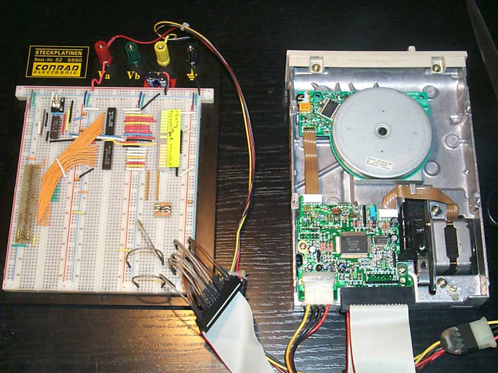
To become sure that a valid jumper setting or modification was found, each drive was tested with the help of a bread board. By manually setting different signals on the IBM modified Shugart bus (the way FDDs are connected to IBM-PC compatible motherboards), each single drive shown here was verified to spin at 300 rpm.
FDD bus signal 2, »Density Select«
Sometimes, a decent FDD is already configured so that it is able to spin at 300 rpm. But this heavily depends on the bus interface line No. 2 [4], used by the Floppy Disk Controller (FDC) to signal the drive whether to operate at 300 rpm (Low Density formats like DD or QD), or at 360 rpm.
But to work properly with the Disk2FDI software, the FDD must spin at 300 rpm independently from the »Density Select« signal. So if a drive can only be jumpered to (automatic) 300/360 mode, it needs to be decoupled from this interface line No. 2.
Teac manufactured Floppy disk drives
This section describes the modifications to several revisions of the well known Teac High Density disk drive type »FD-55GFR«. Teac's support information site contains several PDF documents describing the jumper settings [5,6,7,8].
All (most?) Teac FDDs can be jumpered to automatic 300/360 mode by setting the »I« jumper. To decouple the drive from the »Density Select« bus line, pin No. 2 of the bus connector needs to be isolated with some adhesive tape. Since bus line No. 4 is not used in general and since bus lines 1 and 3 are grounded as all other odd numbered pins, all pins numbered 1 to 4 can be taped, which is much easier to do. Now the drive constantly spins at 360 rpm again, which can be fixed by additionally applying the »LG« jumper. This jumper inverts the behaviour of the »Density Select« line and ensures that the drive constantly spins at 300 rpm.

[Teac FD-55GFR 149-U, 120KB]
Teac FD-55GFR 149-U
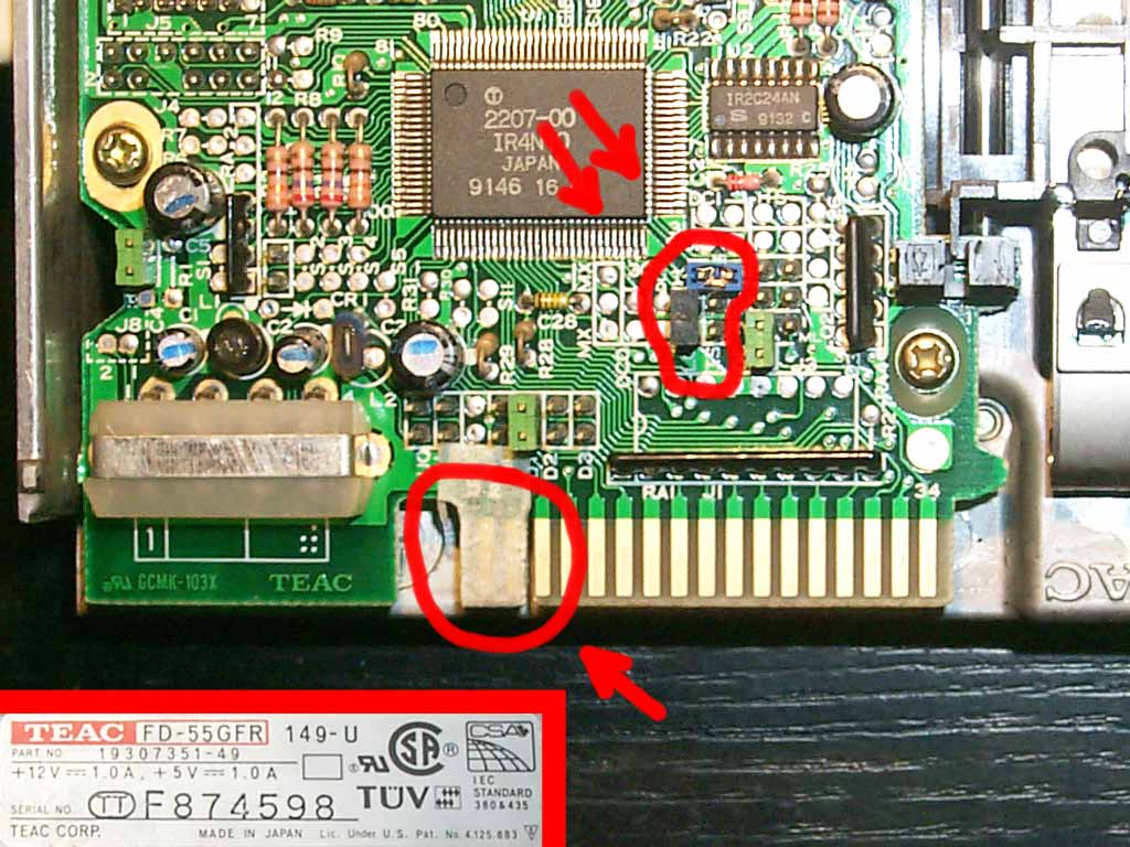
In the picture to the left, look for the right jumper locations circled by a red line. The blue jumper is set to the »I« jumper location. The black jumper sets the »LG« configuration option. By default, only the green jumpers are applied to this floppy disk drive revision. Finally isolate bus lines 1 to 4 as shown by the second red circle. Bus lines 1 to 4 can easily be located by looking for the notch between bus lines 3 and 5 respectively 4 and 6.
[Teac FD-55GFR 193-U, 134KB]
Teac FD-55GFR 193-U
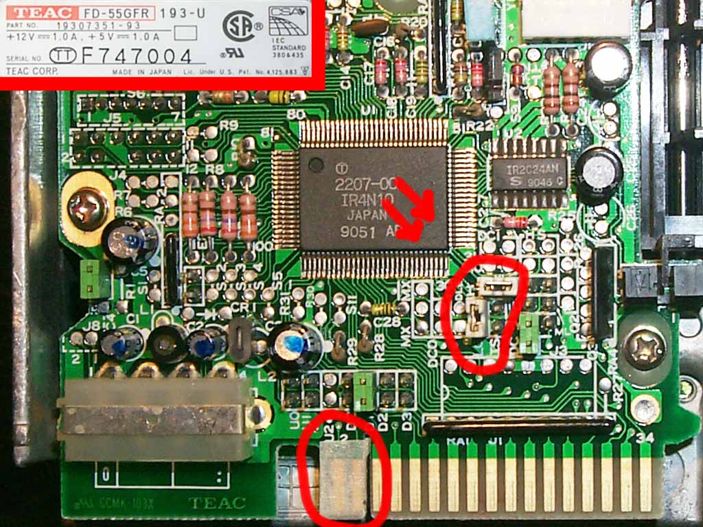
The jumper settings are almost the same as for the 149-U revision, so read the description from the previous subsection. In the picture to the right, look for the two white jumpers. Once again, all green jumpers are set by default for IBM-PC compatible drive operation. Don't forget to isolate bus lines 1 to 4 with some adhesive tape.
[Teac FD-55GFR-570-U, 96KB]
Teac FD-55GFR-570-U
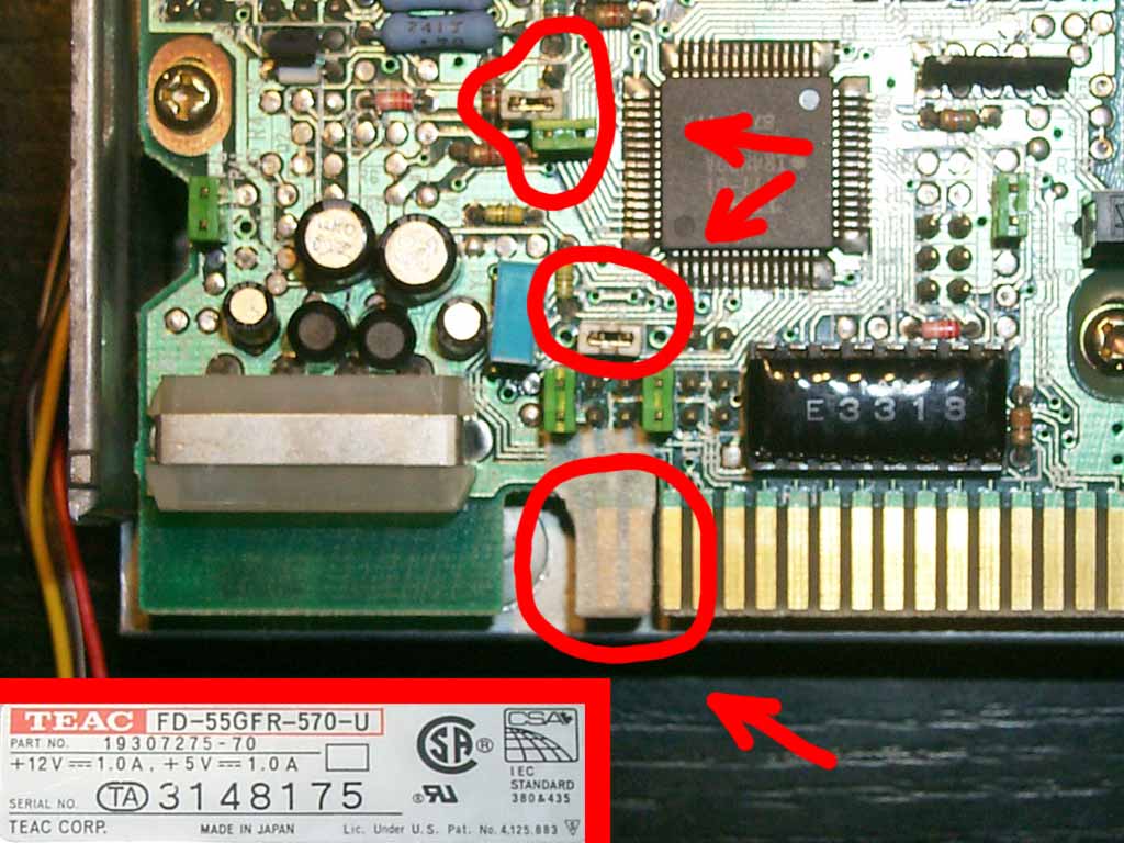
You can locate the »LG« jumper within the red circle in the middle of the picture to the left. It needs to be set the same way as with all previous drive models.
With this drive revision, the »I« jumper is not a standalone type, but selectable between the three positions »II«, »I« and »IS«. Locate this jumper in the picture to the left within the top red circle. Remove the green jumper from its default position »II« and place it to position »I«. In the picture displayed, the green jumper was replaced by a white jumper set at position »I«.
Finally, isolate bus lines 1 to 4.
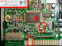
[Teac FD-55GFR 7193-U, 98KB]
Teac FD-55GFR 7193-U
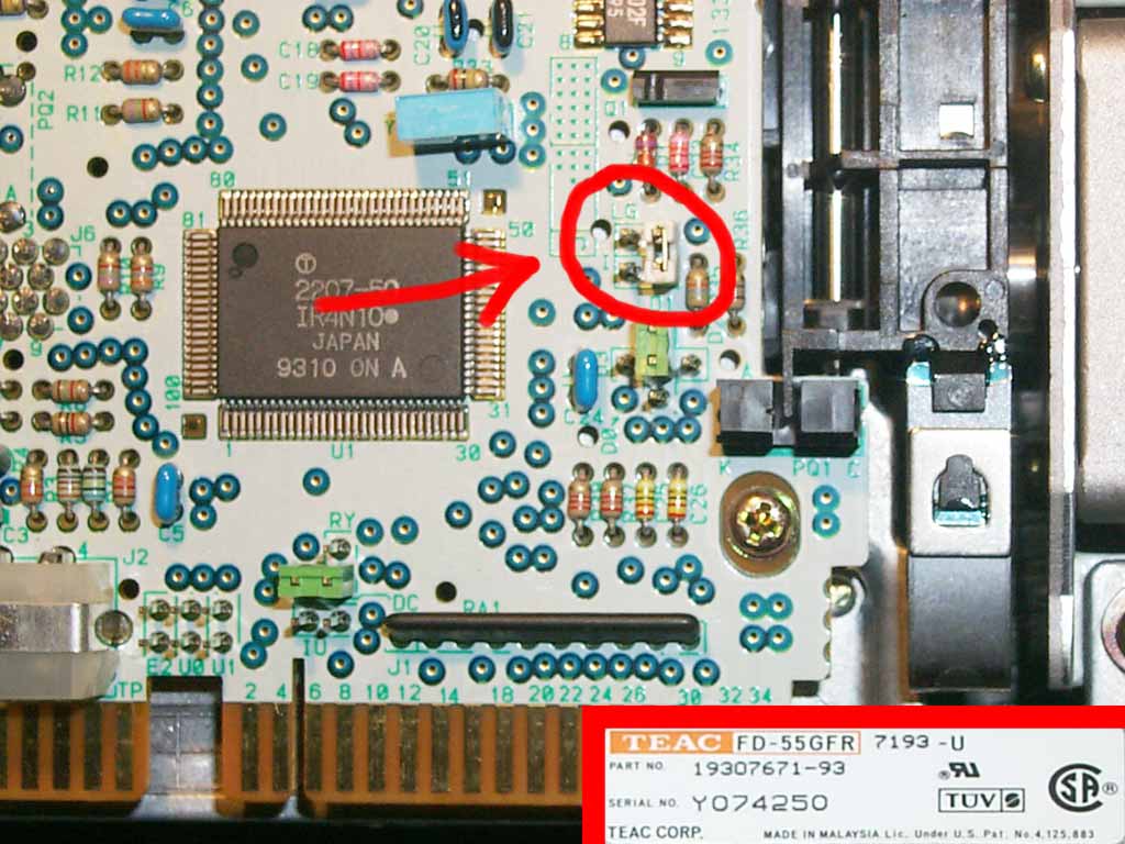
This drive type is the easiest to configure since a single undocumented jumper can be set to get all three modifications done.
Locate the jumper block consisting of both the jumpers »I« and »LG« (see red circle in the picture to the right). Get a new jumper and connect one pin of the »I« pin header with one pin of the »LG« pin header as shown in the picture. It's important to connect the correct pins together.
This modification puts one pin of the »I« jumper to the low logic level (the selected »LG« pin is connected to ground). With this setting, you don't need to isolate bus line No. 2 since the drive spins at 300 rpm regardless of the logic level applied to »Density Select«.
Alternative settings for revision 149-U and 193-U
The undocumented, but simpler jumper setting of the 7193-U revision could also be applied to the drive revisions 149-U and 193-U. The disadvantage is that this wouldn't be possible with a simple jumper. To get the correct pins connected together, you need to connect one of the »I« pins to ground with a short wire. To find the correct pin, simply try out both pins and listen for the drive motor sound.
Applying a switch to manually select between 300 rpm and 360 rpm
If you want to use your 5,25" disk drive not only for Disk2FDI, but also to handle PC formatted disks the usual way, it may be useful to add a little switch. Then you can manually select between both rotation speeds of 300 rpm (Disk2FDI usage) and 360 rpm (accessing standard disks).
To accomplish this task, simply replace the »LG« jumper by your switch (via a wired pinhead connector). Take note that all other settings (bus line 2 isolation and »I« setting) must remain intact when the switch is applied.
With the 7193-U revision, replace the undocumented jumper setting with the switch.
Other floppy disk drive settings
Currently, no FDD from other manufacturers were investigated or tested to see if and how they can be set to a fixed 300 rpm operation (see [9] for FDD jumper settings from different manufacturers). Still, there is a more general alternative to get your floppy disk drive rotating at 300 rpm.
When looking at the bottom side of your FDD, you should mostly see two printed circuit boards (PCB). One of it holds the main control logic and also contains the floppy bus connector. The other PCB is part of the main drive motor, which should be a direct driven type (not a belt driven one, which is not applicable here).
Check the cable between the main logic PCB and the motor PCB: it should be a 4- or 5-wire flat cable with the following signals (get a voltmeter and do some checks to get the right matching):
- +12V
- GND (ground resp. 0V)
- Motor-On
- +5V (sometimes not connected, e.g. for a 4-wire cable)
- Speed-Select
Now, if you disconnect the »Speed-Select« signal from the main control logic PCB, the drive motor should spin at 300 rpm. Because then it cannot be controlled by the main logic PCB, the drive will always rotate at 300 rpm independently from any jumper setting or the »Density Select« bus signal.
The drive motor still may not change its rotation speed, in which case you should carefully check out what happens if you apply a high or low logic level onto this line. Do not set a low or high logic level to this line directly. Better use a 470Ω resistor (390Ω...1KΩ) to connect the »Speed-Select« line to either ground or +5V. So you can find out the correct 300 rpm setting without potentially damaging the drive electronics. See [10, 11] for a more insight view to FDD drive motor controllers.
References (URLs were last visited/validated 2003-12-31)
-
Disk2FDI homepage
-
Catweasel ISA online manual,
with the description of how to modify an IBM-PC/AT style floppy
disk drive so that it can read »flipped« disks
-
Catweasel MK3 product page
-
PC XT/AT Floppy Disk Controller pinout
-
Teac Online reference manuals, FDD configuration
-
Teac FD-55GFR floppy disk drive manual
-
Teac Floppy Drives Knowledgebase
-
Detailed jumper description of the Teac FD-55GFR 149-U
-
Dell computer's support page
with many technical information (jumper descriptions) about
hundreds of computer components and several floppy disk drive
types
-
Rainer Buchty's »Casiorama« FDD modification
page,
describing 3,5" FDD rotation speed adjustments as well as
Shugart bus and derivative cable pinouts
- Rohm BA6492BFS FDD spindle motor driver, look out for the electrical characteristics of the »revolving speed switch voltage« as described on page 560
Copyright and License information
This web article as well as all integrated and externally linked pictures is © 2004 Wolfgang Moser. Contact the author via his web visiting card.
This web article is version 1.0, dated to January 01, 2004.
This web article, version 1.0, as well as all integrated and externally linked pictures is licensed non-exclusively to Vincent Joguin for inclusion inside the official Disk2FDI distribution packages, currently primarily available from the Disk2FDI web site. This license explicitly grants Vincent Joguin the right to include offline representations of this web article into the commercial and non-commercial distribution packages of the Disk2FDI software.
Future versions of this web article, as well as all integrated and externally linked pictures may be published on the author's »Rest In Pieces« web projects web site or a dedicated subsection of the main 1581-Copy homepage. Future versions of this web article, as well as all integrated and externally linked pictures may be published under an Open-Source like license.
Page jump links:
Heading
Disk2FDI
Analyzing FDD electronics and bus signals
Teac manufactured Floppy disk drives
Other floppy disk drive settings
References
Copyright and License information